The first version of this wind station used a traditional mechanical wind-speed and direction sensor. Its moving parts produced analogue signals, read through a differential ADC module. That was a useful prototype: it established the mounting, wiring and data path, and proved that wind belonged in the wider sensor network.
For a permanent outdoor installation, however, I wanted to remove the mechanical stage. Bearings, cups and vanes are all exposed to weather and wear. The replacement is a Veinasa CXS02B-N two-in-one ultrasonic wind sensor, which measures wind speed and direction without moving parts and reports the result digitally.
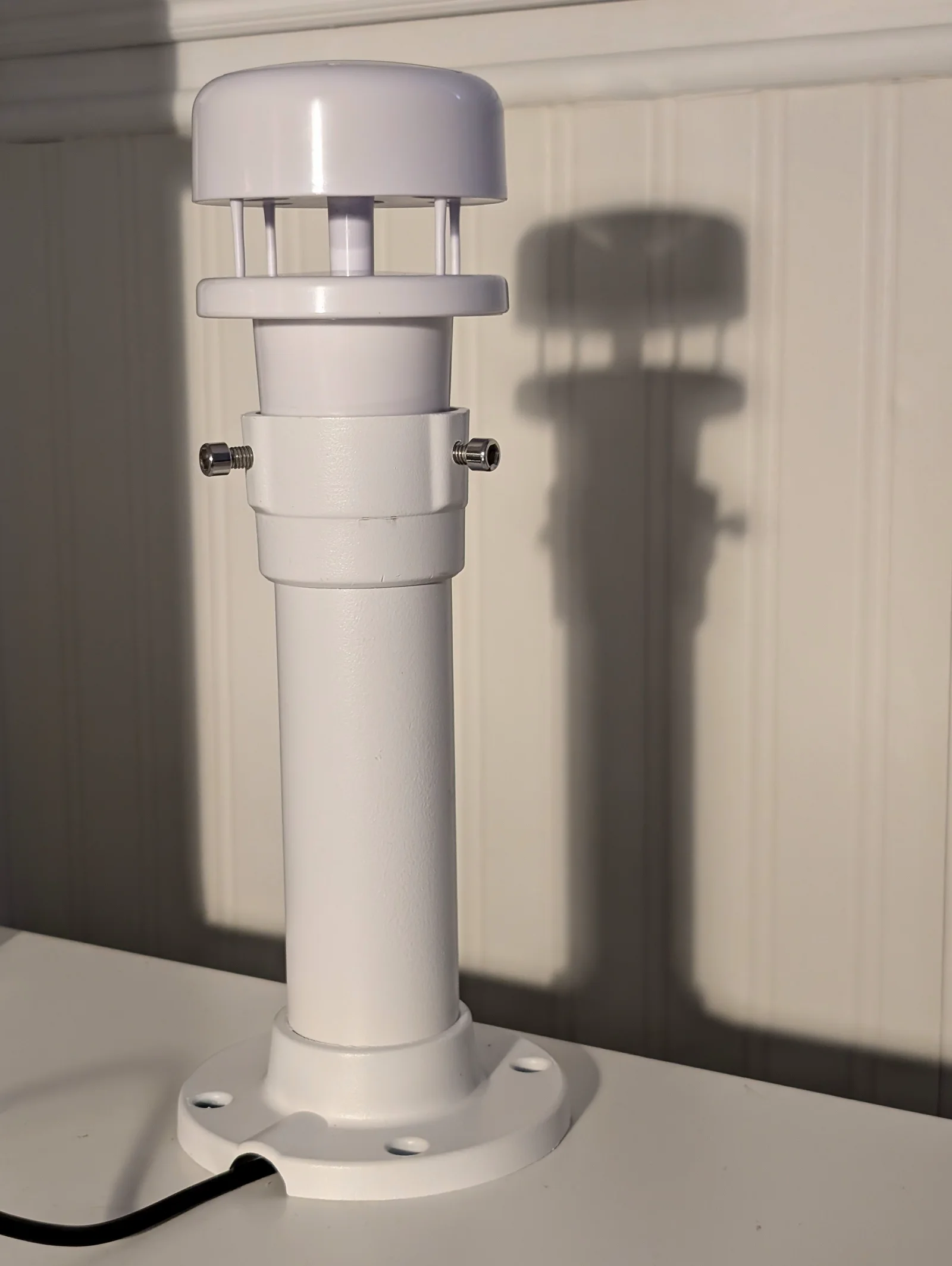
Sensor at a glance
| Specification | Value |
|---|---|
| Model | Veinasa CXS02B-N |
| Measurement principle | Ultrasonic; no moving parts |
| Wind-speed range | 0–40 m/s |
| Wind-speed accuracy | ±3% at 25°C |
| Wind-speed resolution | 0.1 m/s |
| Wind-direction range | 0–359° |
| Wind-direction accuracy | ±3° at 25°C |
| Wind-direction resolution | 1° |
| Tested electrical interface | Two-wire RS485 |
| Tested protocol | NMEA-0183 MWV ASCII |
| Tested serial configuration | 9600 baud, 8 data bits, no parity, 1 stop bit |
| Product-family baud range | 4800–19200 baud |
| Supply | 5–24 V DC |
| Power consumption | 0.2 W |
| Protection | IP65 |
| Operating temperature | −40°C to +60°C |
| Storage temperature | −50°C to +80°C |
| Operating humidity | 0–100% RH |
| Dimensions and weight | Ø82 × 108 mm; 0.2 kg |
| Housing material | ASA engineering plastic |
The migration was deliberately split into two steps. I first connected the sensor to Linux with a USB–RS485 adapter, where the raw protocol could be inspected and tested quickly. Once that path was understood, I replaced the USB adapter with a small TTL–RS485 converter and a Waveshare RP2040-ETH module that happened to be available on the bench. The eventual goal is a compact RP2040-based outdoor node that carries both power and data over the site’s PoE infrastructure; the final controller hardware will most likely be a different unit.
Why change the sensor?
The ultrasonic unit is specified for wind speeds from 0 to 40 m/s, with 0.1 m/s resolution, and direction across 0–359°, with 1° resolution. Its stated power consumption is 0.2 W, its supply range is 5–24 V DC, and its enclosure is rated IP65. The product family is offered with several mutually exclusive electrical interfaces, including analogue, RS232, RS485 and SDI-12 outputs. Its digital versions are available with protocols including Modbus and NMEA-0183.
The unit used here combines the RS485 electrical interface with the NMEA-0183 protocol. That distinction matters: a listing that describes every available option does not mean one sensor presents all of those interfaces and protocols at once. The tested sensor produces an ASCII NMEA wind sentence at 9600 baud, 8 data bits, no parity and one stop bit.
Compared with the earlier differential ADC arrangement, the digital link moves more responsibility into the sensor but gives the collector a much better boundary. Each measurement arrives as a framed, human-readable record with its own checksum. The receiver can distinguish a valid zero-wind reading from a damaged or incomplete transmission instead of merely accepting an ADC value.
Stage one: establish the protocol over USB
The first test used the same sort of USB–RS485 adapter that would normally be attached to a Linux system. The sensor’s A and B conductors connected to the adapter’s differential terminals, and the serial port was configured for 9600 8N1.
The sensor sent sentences like this approximately once per second:
$WIMWV,286,R,4.2,M,A*34This is an NMEA MWV wind sentence. Its fields mean:
286— direction in degrees;R— relative wind reference (Twould mean true);4.2— wind speed;M— metres per second (KandNrepresent km/h and knots);A— the sensor considers the measurement valid (Vmeans invalid);34— the transmitted hexadecimal checksum.
The checksum is the byte-wise XOR of every character between $ and *. Checking it locally proves that the complete sentence crossed the serial link intact. The separate A status then says whether the sensor considers the underlying measurement valid.
I built a small portable C parser during this stage. It has no operating-system dependencies, performs no heap allocation and accepts bytes incrementally, so exactly the same parsing and validation logic can run in a Linux test program and on a microcontroller. Native tests cover framing, fields, numeric ranges, units and checksum failures before the parser ever sees live hardware.
This USB phase was valuable because it separated the sensor protocol from the embedded system. Readable ASCII from Linux proved the RS485 polarity, line settings and sentence format independently of any RP2040 pin configuration.
Stage two: move the receiver onto an RP2040
The embedded proof of concept uses the available Waveshare RP2040-ETH and a D93 TTL–RS485 conversion module. This board is test hardware rather than a commitment to the final deployment platform. The sensor remains on the differential side of the converter; the RP2040 receives the converter’s single-ended UART output.
On this particular D93 board, oscilloscope measurements were more useful than assumptions about labels. The terminal marked RX pulsed in exact synchrony with the module’s receive LED, while TX remained idle. The working receive-only connection is therefore:
Sensor RS485 A  -> D93 A
Sensor RS485 B  -> D93 B
D93 RX          -> RP2040 GP1 / UART0 RX
D93 GND         -> RP2040 GND
The converter’s TTL side must use a voltage safe for the RP2040’s 3.3 V GPIO. RS485 A and B must never be connected directly to a microcontroller UART: they are a differential bus and require the receiver in between.
The D93 labelling caused a useful detour. Generic advice often says to cross UART names—converter TX to microcontroller RX—but labels on converter boards are not consistent about perspective. Here, directly observing the pins established that the D93 RX terminal was the signal to feed into GP1. The lesson is not that RX-to-RX is universally correct; it is that a schematic, manual or measurement outranks a naming convention.
There was a second, independent trap. Initial firmware listened at 115200 baud, so the RS485 activity LED flashed and an oscilloscope showed a real waveform, yet the UART produced no useful bytes. The sensor manual specifies 9600 baud. Once the RP2040 UART matched 9600 8N1, valid ASCII appeared immediately:
$WIMWV,0,R,0.0,M,A*3EAn activity LED proves that something is happening on the bus; it does not prove that the downstream UART is connected to the correct logic output or sampling it at the correct rate.
Parse at the edge
The RP2040 firmware now feeds every byte received on GP1 into the same stream parser used by the Linux prototype. A newline completes a candidate frame. Valid frames are parsed and normalized to metres per second; invalid frames produce an explicit parser error rather than becoming measurements.
The complete parser, native tests, Linux reader and tested RP2040 firmware are available in the ultrasonic_wind_sensor repository. The deployable example is RP2040WindReader.ino; the README includes its Arduino CLI build command and GPIO1 wiring notes.
The USB serial console emits one compact line per received measurement:
direction_deg=285.0 speed_mps=1.8 data_valid=yes checksum_valid=yes
direction_deg=289.0 speed_mps=2.7 data_valid=yes checksum_valid=yes
direction_deg=290.0 speed_mps=3.0 data_valid=yes checksum_valid=yes
direction_deg=288.0 speed_mps=3.2 data_valid=yes checksum_valid=yes
A longer live run showed direction changing from the high 200s through 221° and back while wind speed rose from 0.0 to 3.2 m/s. Every displayed record carried the sensor’s valid status and passed the locally calculated checksum. The initial repeated zeroes were genuine valid measurements, not a dead serial connection:
direction_deg=268.0 speed_mps=0.0 data_valid=yes checksum_valid=yesKeeping the edge output this simple makes the next integration step predictable. Downstream software does not need to know where commas sit in an MWV sentence or how NMEA checksums work. It receives a complete, validated measurement per line, while malformed serial data remains visible as an error instead of contaminating the history.
Toward the permanent PoE node
USB remains useful for firmware installation and diagnosis, but it is not the intended permanent transport. The production node will use an RP2040-based controller selected for the final installation, not necessarily the Waveshare RP2040-ETH used for this test. With wired networking and power supplied through the site’s PoE arrangement, the outdoor installation can use one network cable for power and connectivity while keeping the RS485 run local to the wind sensor.
The resulting path is:
Ultrasonic wind measurement
        -> RS485 A/B
        -> D93 receiver
        -> RP2040 UART on GP1
        -> NMEA framing and checksum validation
        -> parsed wind measurement
        -> Ethernet / PoE-connected sensor network
That is a cleaner permanent architecture than carrying the original analogue signals back to a differential ADC. The sensor owns the ultrasonic measurement, RS485 provides a robust local field link, the RP2040 rejects damaged frames and converts the protocol into a small structured record, and Ethernet carries those records into the rest of the system.
The two-stage bring-up also leaves a reproducible troubleshooting route. If the installed node ever stops reporting, the RS485 side can be returned to the known-good Linux USB adapter, the TTL output can be checked with an oscilloscope, and the raw NMEA sentence can be tested with the same parser. Each layer has a clear input, output and independent way to prove that it works.