Reliable outdoor measurements begin with a surprisingly practical problem: the sensor has to live outside, but the electronics and cable entry still need protection from rain, condensation, freezing temperatures, and sunlight. This project adds two related measurement points to the sensor network: outdoor air temperature and humidity, plus temperature probes at the ground surface and one metre underground.
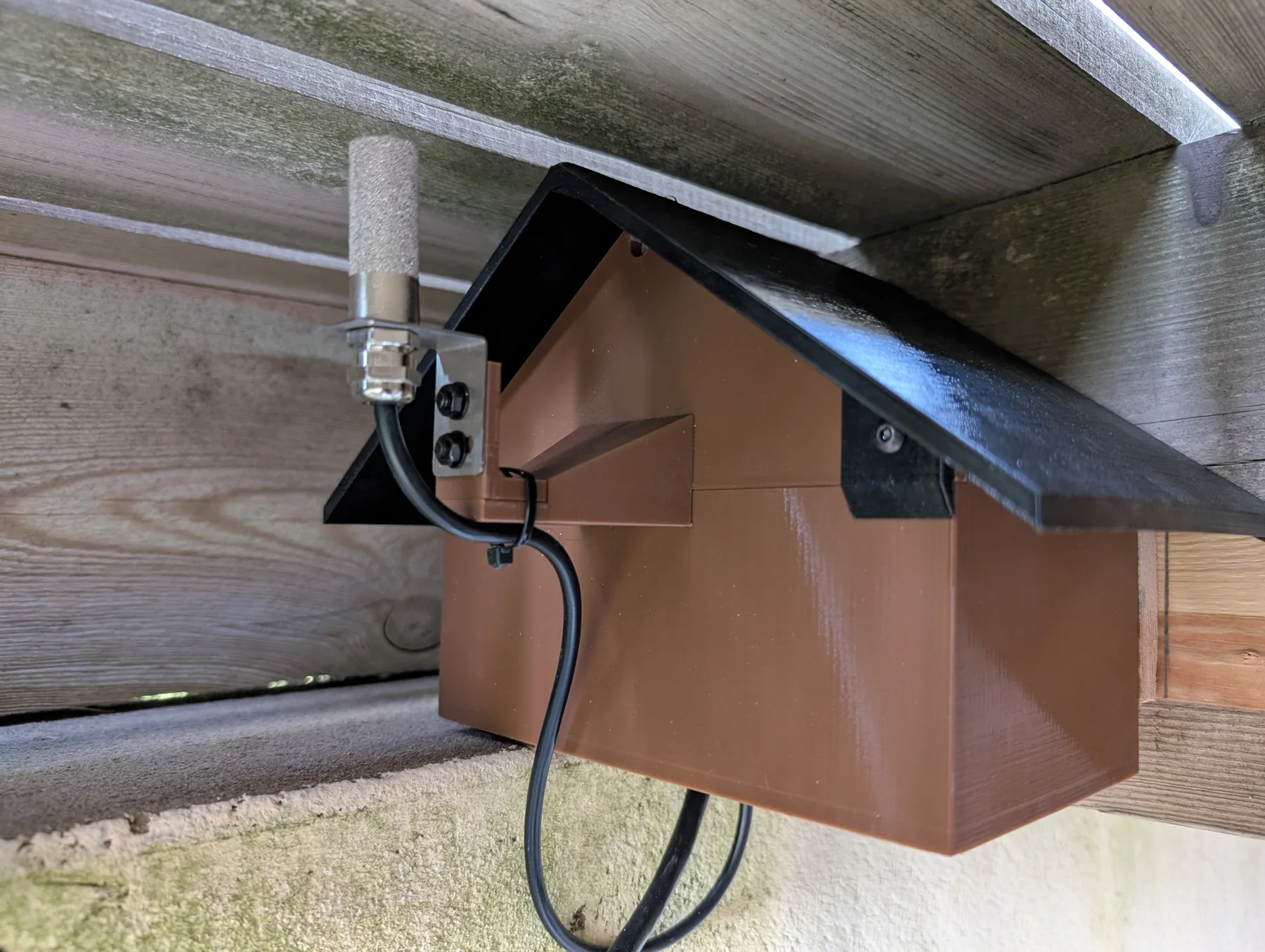
The air sensor is intended to measure the ambient conditions in a representative location: in the shade, away from the house wall, and protected from direct weather exposure. The enclosure is printed in PETG and shaped as a small weather shelter. It gives the sensor a stable physical home without placing it directly against a warm wall or leaving the electronics exposed.
The outdoor sensor house
The enclosure is a custom PETG print. The two controller designs use different internal reference sensors. The outdoor air/humidity unit uses a Bosch BME280 over software SPI; it reports the enclosure’s temperature, relative humidity, and barometric pressure. The ground-temperature unit uses a Sensirion SHTC3 over I²C for its internal temperature and humidity reference. These internal readings are useful for checking whether moisture and cold are being kept under control, rather than treating the enclosure as an invisible assumption.
A more robust second sensor house
The second sensor house uses a more substantial construction for long-term outdoor exposure. Its installation location is more exposed to wind, so it has an octagonal shape and is printed from 6 mm PETG, giving the walls more material and stiffness than the first enclosure.
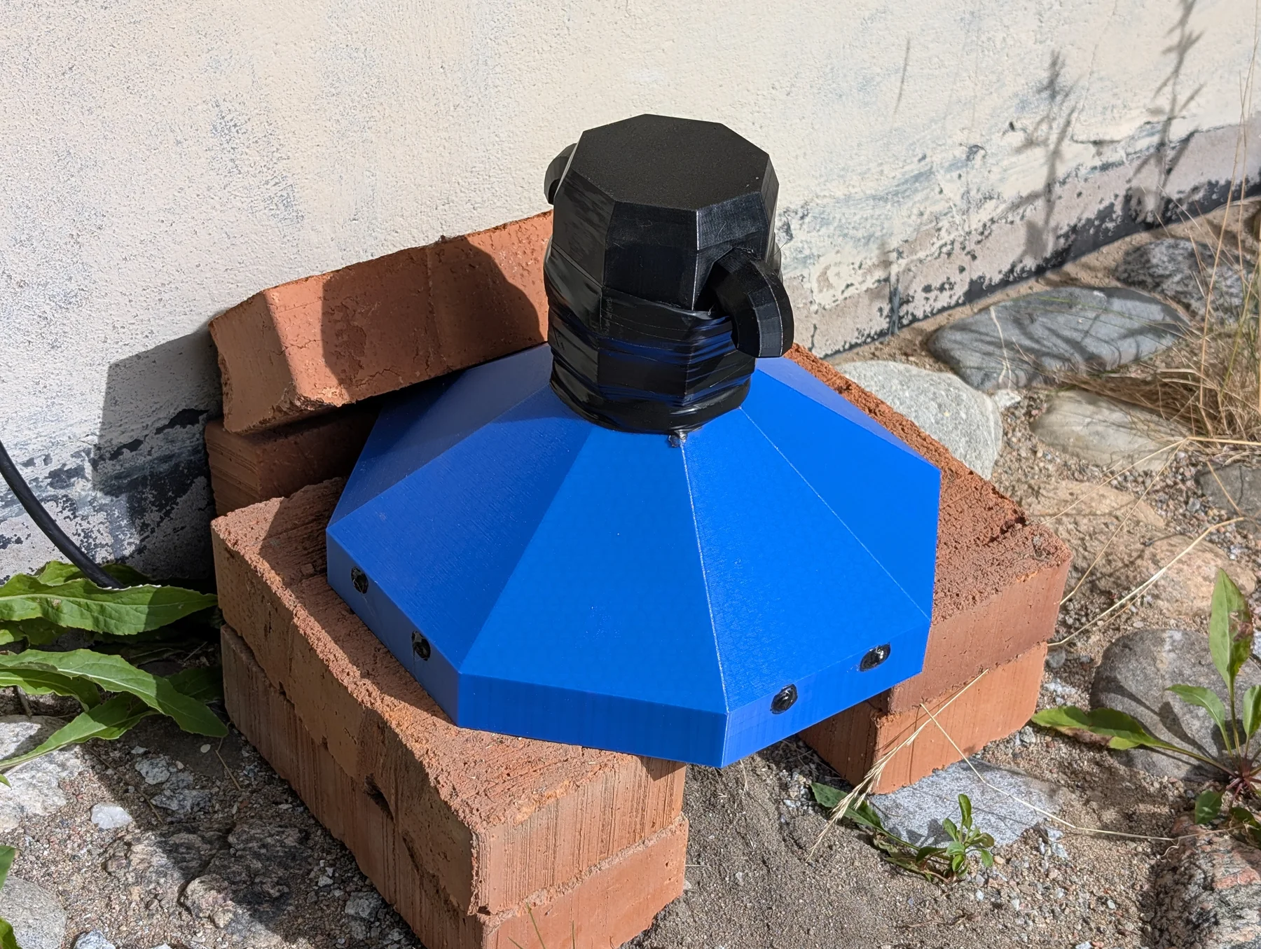
Ventilation is handled as a weather-protected system rather than an open hole through the case. There is an air gap underneath the house, and the tower includes vents with two angled openings facing in opposite directions. This allows air exchange while making it more difficult for wind-driven rain to enter directly.
The inside walls of the tower are coated with epoxy resin as an additional water barrier. Outside the enclosure, vinyl tape provides another layer of cover, while a glue gun was used around the M4 screws to reduce the effect of wet weather at the fasteners. The finished house is raised vertically on bricks, keeping it away from ground splash and allowing air to move underneath it.
Heating each sensor house
Each sensor house has one small PTC heating unit to reduce the risk of cold and condensation during winter. The selected part is a 35 × 20 × 5 mm PTC heating element, specified for 5 V, approximately 40 °C, and 2–5 W. Each PTC heater is combined with several heatsinks to spread the heat through its enclosure instead of concentrating it at one small surface. Its thermostatic behaviour makes it a simple way to add gentle heat without turning the box into a high-temperature chamber.
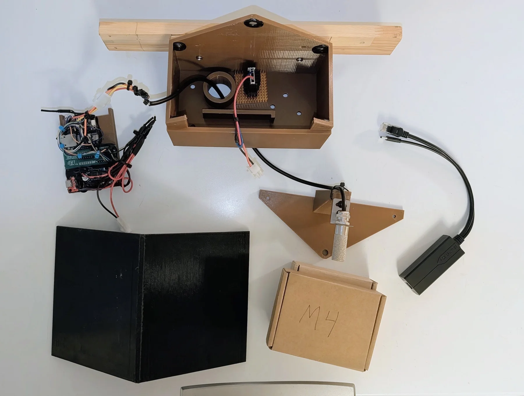
The heater is not intended to make the measured air artificially warm. The point is to keep the enclosure and electronics in a more controlled condition while the sensor arrangement remains exposed to the outdoor environment it is meant to describe. The internal reference reading provides a way to see how effective that compromise is.
Barometric pressure is part of the data set
The BME280 means that the outdoor air unit is not only a temperature and humidity node. It also reports barometric pressure to the sensor system once per minute. The PETG house can affect the local temperature and humidity around the electronics, but it should not materially affect pressure: air pressure equalizes through the enclosure openings, so the housing is not intended to create a pressure offset. Pressure is recorded alongside the other channels, giving the system a useful atmospheric trend in addition to the outdoor air readings. The pressure channel will be examined together with the other measurements in the statistics section.
Sensor summary
| Measurement path | Sensor and interface | Role in this installation | Useful high-level specification |
|---|---|---|---|
| Outdoor air | Sensirion SHT3x, I²C | Air temperature and relative humidity outside the house | The SHT3x family provides calibrated digital temperature/humidity output over I²C; the exact accuracy depends on the SHT3x variant. See the SHT3x-DIS datasheet. |
| Ground-unit enclosure reference | Sensirion SHTC3, I²C | Temperature and humidity inside the heated enclosure | −40 to +125 °C, 0–100%RH, typical ±0.2 °C and ±2%RH, 1.62–3.6 V supply. See Sensirion’s SHTC3 specification. |
| Shallow and deep ground | PT1000 RTD, three-wire, read by MAX31865 | Temperature just below the surface and at 100 cm | A PT1000 is a nominal 1 kΩ platinum RTD; the MAX31865 board is configured for 1 kΩ RTDs with a 4.3 kΩ reference resistor. See the MAX31865 guide. |
| Air-unit enclosure reference | Bosch BME280, software SPI | Internal temperature, humidity, and barometric pressure | −40 to +85 °C, 0–100%RH, 300–1100 hPa, with SPI/I²C interfaces. See the BME280 datasheet. |
These are component-level specifications, not a promise that every installed reading has that accuracy. Enclosure geometry, cable length, thermal gradients, sensor placement, soil contact, and calibration all influence the final measurement.
Outdoor Ethernet and PoE protection
The sensors are connected using gel-filled outdoor Cat6 Ethernet cable. This cable is made for outdoor exposure, but its construction also makes termination less forgiving: the cable is thick enough that a normal RJ45 adapter is too small for the individual conductors.

The selected adapter is designed for the larger conductors. The cable is terminated using the T568A standard and checked with a cable tester before it is connected to the rest of the network.
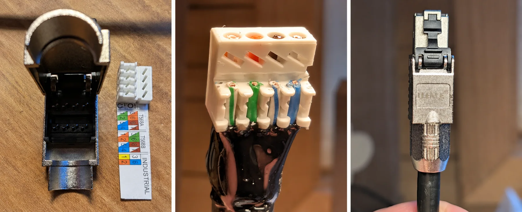
Where the cable enters the house, an RJ45-to-RJ45 adapter joins it to a shorter indoor Ethernet cable. The indoor cable is much easier to bend, route through holes, and fit into ordinary cable-management systems. Using the rugged outdoor cable only where it is needed, then transitioning to flexible indoor cable, makes the installation easier to service without compromising the exposed run.
The outdoor runs pass through a PROCET PT-PR04G Ethernet Surge Protector. It supports 10/100/1000 Mbps Ethernet and IEEE 802.3af/at/bt or PoE++-class power, with protection specified up to 20 kV common-mode surge voltage and 1.5 kV differential-mode surge voltage. Its stated operating range is −40 °C to 85 °C, which suits the same outdoor environment as the cable.
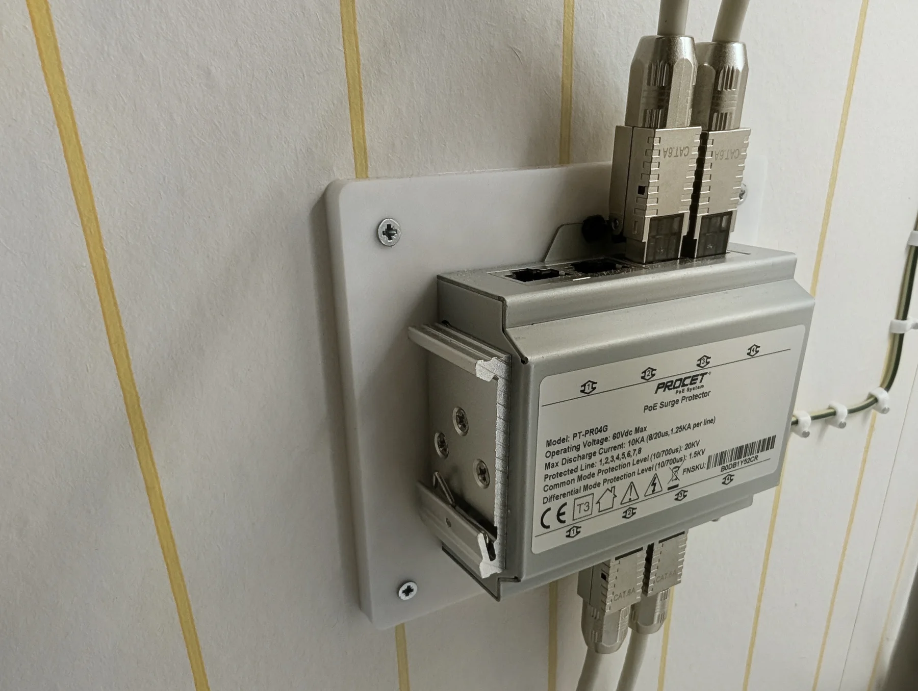
The surge protector is mounted before the outdoor cable continues to the sensor. I designed a custom wall-mounting adapter for it and printed the adapter in white PETG, giving the protector a rigid, purpose-built fixing at the cable entry. It provides a defined place for the exposed run to meet the building-side network, rather than relying on an improvised junction.
Installing the cables and probes
The cable installation is relatively straightforward once the termination method is settled. A hole is drilled for the outdoor cable, the run is secured, and the indoor transition is routed through the existing cable-management path.
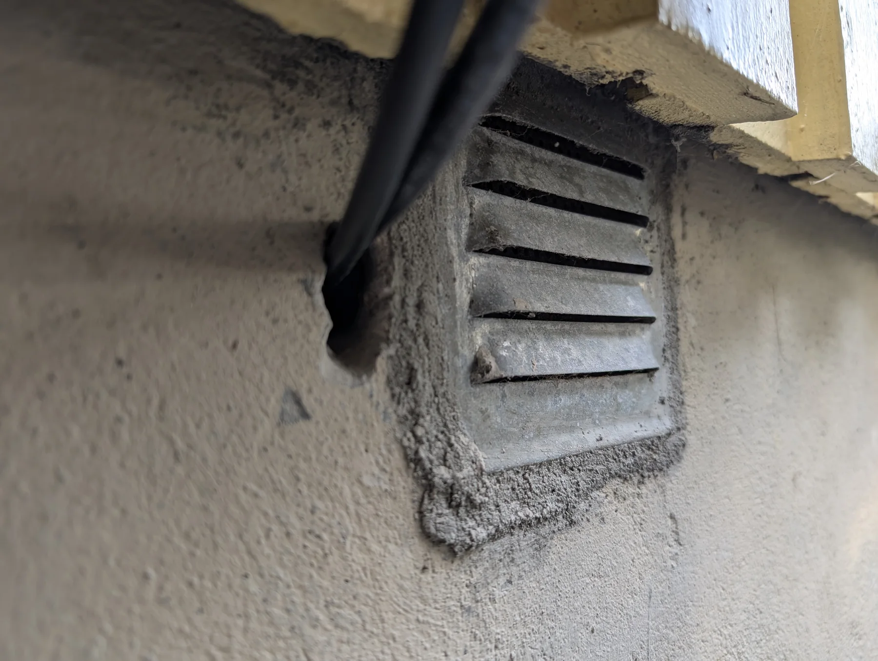
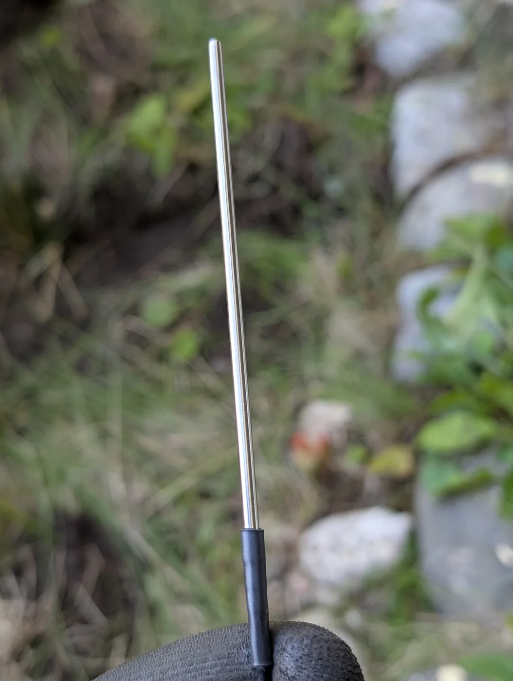
The ground probes require more physical work. The shallow probe is placed below the top few centimetres of soil, while the deeper probe needs a narrow hole reaching one metre. The probes are placed, the hole is filled with soil, and additional soil is added after rainfall has settled the installation.
|
|
||||||||||||
This installation order matters because the ground is part of the measurement system. The probe must be surrounded by soil again rather than left in an air gap, and the final readings should be interpreted after the disturbed area has had time to settle.
The next part of the article will use the collected data to compare the outdoor air, near-surface ground, and one-metre underground measurements over time.
A short view of the one-metre ground-sensor installation.